⚓ Monograph Overview: The Art of Guiding Ships by the Stars
Before the advent of satellite constellations, oceanic wayfinding relied upon deciphering the geometry of the heavens. From the primitive mariner’s astrolabe and quadrant used during the Age of Discovery to the mathematical elegance of the cross-staff, back-staff, and the double-reflecting nautical sextant, celestial navigation enabled explorers to chart uncharted oceans and link distant continents.
For thousands of years, the open ocean represented an insurmountable barrier to human movement. To venture beyond sight of familiar headlands was to enter a realm devoid of terrestrial landmarks, where ocean currents, prevailing winds, and shifting cloud cover obscured all sense of location. In this trackless expanse, the celestial dome provided the only immutable coordinate system on Earth. The rhythmic rotation of the starry sky, the diurnal transit of the sun, and the subtle variations of the moon offered an eternal cosmic compass for those who possessed the mathematical and instrumental skill to read them.
The history of celestial navigation is the history of humanity’s quest for instrumental precision. It chronicles the evolution from crude weighted plumb-lines and wooden cross-staffs to the optical mastery of split-mirror vernier sextants capable of measuring angular altitudes down to fractions of an arcminute. By unlocking the relationship between celestial coordinates and terrestrial geography, navigation ceased to be an intuitive craft and transformed into an exact maritime science that propelled the European Age of Discovery, opened trans-oceanic trade routes, and enabled the mapping of planet Earth.
1. The Foundations: Latitude and the Celestial Sphere
The mathematical basis of celestial navigation rests upon the concept of the celestial sphere—an imaginary concentric sphere of infinite radius surrounding the Earth, onto which all stars and heavenly bodies are projected. Because the Earth’s rotational axis aligns almost directly with the star Polaris (Alpha Ursae Minoris, the North Star) in the Northern Hemisphere, observing this star provides an immediate calculation of geographic latitude.
The angular altitude of Polaris above the true horizon is mathematically identical to the observer’s latitude on the Earth’s surface:
Latitude (φ) = Measured Altitude of Polaris (H) ± Corrections (Index, Dip, Refraction)
If an observer measures Polaris at an altitude of exactly 35 degrees above the northern horizon, their ship is situated along the 35th parallel North. In the Southern Hemisphere, where no bright star marks the celestial pole, navigators utilized the constellation of the Southern Cross (Crux), measuring the altitude of its pointer stars (Alpha and Beta Centauri) and calculating latitude through tabular declination offsets.
The Meridian Solar Transit
While stellar navigation provided latitude at twilight and night, daytime navigation relied upon the meridian transit of the sun. As the sun climbs through the morning sky, it reaches its highest angular altitude at the precise moment of local solar noon, when it crosses the observer’s celestial meridian due north or due south.
By measuring this peak noon altitude (Ho) with an instrument and referencing the sun’s seasonal solar declination (d)—the geographic latitude over which the sun stands directly overhead on that date, tabulated in astronomical tables—the navigator calculates latitude with elementary arithmetic:
Latitude (φ) = 90° – Ho + Declination (d)
| Historical Instrument | Century of Origin | Primary Optical Principle | Typical Angular Error | Key Operational Limitation |
|---|---|---|---|---|
| Mariner’s Astrolabe | 15th Century (Portugal) | Gravity plumb suspension with sighting alidade | ± 2° to 4° (120–240 miles) | Excessive swinging on pitching ship decks |
| Cross-Staff (Jacob’s Staff) | 14th / 16th Century | Linear eye-to-vane parallax alignment | ± 1° (60 miles) | Forced mariner to look directly into glaring sun |
| Back-Staff (Davis Quadrant) | 1594 (John Davis) | Shadow projection behind navigator’s sightline | ± 15 to 30 arcminutes (15–30 miles) | Dependent on strong direct sunlight for shadow casting |
| Octant (Hadley’s Quadrant) | 1731 (John Hadley) | Single reflection mirror mechanism (45° arc) | ± 1 to 2 arcminutes | Limited to measuring angles up to 90 degrees |
| Nautical Sextant | 1757 (John Campbell) | Double reflection split-mirror with vernier arc (60°) | ± 0.1 arcminute (<0.1 nautical mile) | Requires visible horizon line (unusable in fog) |
2. Early Instruments: The Mariner’s Astrolabe and Quadrant
The earliest mathematical instrument adapted for oceanic navigation was the quadrant—a wooden or brass quarter-circle inscribed with a 90-degree scale, fitted with two sighting pinhole vanes along one edge and a weighted plumb-line hanging from the apex. Used by Portuguese navigators exploring the west coast of Africa under Prince Henry the Navigator, the quadrant was simple but suffered severely from ship motion; the slightest roll of the ship set the plumb-bob swinging across the scale, making readings impossible.
To overcome wind resistance, Portuguese instrument makers in the mid-fifteenth century developed the Mariner’s Astrolabe. Unlike intricate land astrolabes used for astrological computations, the mariner’s astrolabe was heavily simplified and cast from solid, dense brass, often weighing five to ten pounds. Its internal disc was perforated with open wheel-like cutouts to allow sea gales to blow straight through without deflecting the instrument.
Operating the Mariner’s Astrolabe
Suspended by a thumb ring to allow gravity to establish a true vertical plumb line, the navigator aligned the rotating sighting arm (alidade) with the sun or star. When observing the sun, the navigator held the heavy instrument at knee level, rotating the alidade until the beam of sunlight passing through a tiny pinhole on the upper vane shone directly onto a matching target pinhole on the lower vane, protecting the navigator’s retinas from solar blindness.
3. The Age of Sail Refinement: Cross-Staff and Back-Staff
Despite its durability, the mariner’s astrolabe was inaccurate on rolling seas. By the early sixteenth century, European mariners adopted the cross-staff (or Jacob’s Staff), an instrument originally developed by Jewish mathematician Levi ben Gerson in fourteenth-century Catalonia. The cross-staff consisted of a square wooden staff approximately three to four feet long, engraved with graduated scales, onto which perpendicular cross-pieces of varying lengths were fitted.
To measure the sun’s altitude, the navigator pressed one end of the wooden staff against their cheekbone beneath the eye and slid the cross-piece along the staff until its lower tip aligned with the sea horizon and its upper tip aligned with the center of the sun. While far more accurate than the astrolabe on an unsteady deck, the cross-staff possessed a terrible medical flaw: navigators were forced to stare directly into the blinding solar disc, causing thousands of navigators to suffer permanent retinal damage and cataracts.
John Davis and the Back-Staff (1594)
In 1594, English Arctic explorer Captain John Davis invented an ingenious solution: the back-staff (known internationally as the Davis Quadrant). The back-staff completely eliminated the danger of solar blindness by utilizing shadow projection.
As the name implied, the navigator stood with their back turned toward the sun. Looking through a sighting vane at the rear of the instrument, the navigator observed the sea horizon through a slotted horizon vane at the front, while simultaneously adjusting a sliding shadow vane along a curved 60-degree arc until the cast shadow of the sun fell directly across the horizon line. Because the navigator never looked at the sun, observation precision improved dramatically, reducing operational error to less than 20 arcminutes.
⚓ Historical Insight: The Origin of the Term ‘Sight Reduction’
In celestial navigation, converting an observed angular reading into a line of position (LOP) is called ‘sight reduction’. Navigators had to reduce the raw sextant angle by applying corrections for index error (instrument alignment), dip of the horizon (height of the navigator’s eye above water), atmospheric refraction (bending of light rays through air), and semidiameter (adjusting from the sun’s limb to its center).
4. The Apex of Precision: The Double-Reflecting Sextant
The ultimate revolution in celestial navigation occurred in the mid-eighteenth century with the development of the double-reflecting optical instrument. Conceived independently by English mathematician John Hadley in 1731 and American inventor Thomas Godfrey in Philadelphia, the octant utilized two mirrors to bring the image of the celestial body and the sea horizon into a single field of view.
In 1757, Royal Navy Captain John Campbell expanded the octant’s 45-degree arc to a 60-degree arc (one-sixth of a circle), creating the modern sextant. Because double reflection doubles the optical deflection angle, a 60-degree arc allows the measurement of angles up to 120 degrees—sufficient to measure lunar distances and high summer noon suns.
Optical Geometry of the Modern Marine Sextant
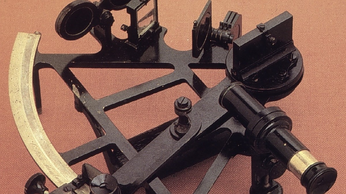
The modern nautical sextant consists of an ultra-rigid metal frame (cast from brass or aluminum), a pivoting index arm carrying a micrometric drum and vernier scale, an index mirror mounted at the pivot axis, and a split-horizon glass mounted on the frame. The horizon glass is split vertically: one half is a mirror reflecting the celestial body from the index mirror, while the other half is clear glass displaying the horizon directly.
As the navigator rocks the sextant gently from side to side, the reflected image of the sun or star appears to hover directly over the true sea horizon. When the bottom edge (lower limb) of the sun touches the horizon line, the navigator records the exact time to the second from a marine chronometer. With precision vernier drums reading down to 0.1 arcminute (one-tenth of a nautical mile), the sextant achieved an optical accuracy that remains unmatched by any other non-electronic navigational instrument.
5. Celestial Navigation in the Digital and Satellite Era
During the nineteenth and twentieth centuries, celestial navigation reached its operational perfection through the development of the Marcq St. Hilaire Intercept Method (1875) and standardized sight reduction tables (such as the British AP 3270 and American HO 229/249). Navigators no longer needed to wait for noon; any sight of any star, planet, or moon at any time of day could be reduced into a precise celestial Line of Position (LOP). Intersecting two or more LOPs provided an absolute geographic ‘fix’ anywhere on the world ocean.
While the launch of satellite navigation—culminating in the Global Positioning System (GPS) in the 1980s—relegated celestial navigation from a primary operational tool to an emergency backup, the discipline has experienced an extraordinary modern renaissance. Recognizing that satellite networks are vulnerable to cyber-attacks, solar geomagnetic storms, electromagnetic pulses (EMP), and space debris collisions, the United States Naval Academy at Annapolis reinstated mandatory celestial sextant training for all naval officers in 2015.
Celestial navigation remains the only completely autonomous, unjammable, and unhackable system of long-distance navigation available to humanity. As long as ships sail beneath the sun, moon, and stars, the ancient art of the sextant will endure as the ultimate maritime bridge between the cosmos and the sea.
6. Mathematical Sight Reduction: The Marcq St. Hilaire Method
The definitive mathematical formulation of modern celestial navigation was published in 1875 by French naval officer Marcq St. Hilaire, known as the Intercept Method. Prior to St. Hilaire, navigators had to solve complex spherical trigonometry equations that yielded accurate lines of position only at precise moments (such as noon for latitude or morning sights for longitude).
St. Hilaire revolutionized the discipline by calculating what altitude the celestial body should have if the ship were at an assumed dead-reckoning position (Computed Altitude, Hc), and comparing that against the actual sextant measurement (Observed Altitude, Ho):
Intercept Distance (p) = Observed Altitude (Ho) – Computed Altitude (Hc)
If Ho is greater than Hc, the ship is closer to the celestial body’s geographic position (GP) by an amount equal to the difference in arcminutes (where one arcminute equals exactly one nautical mile). The navigator draws a straight Line of Position (LOP) perpendicular to the azimuth bearing. By taking three sights on three different stars during evening twilight—such as Vega, Arcturus, and Spica—the intersection of the three LOPs forms a small navigation triangle (‘the cocked hat’), establishing the ship’s true position with absolute precision.
| Celestial Sight Step | Mathematical Operation | Instrument / Reference Table Used | Navigational Output |
|---|---|---|---|
| 1. Angular Observation | Index, Dip, and Refraction Corrections | Marine Sextant with vernier drum | True Observed Altitude (Ho) |
| 2. Ephemeris Lookup | Greenwich Hour Angle (GHA) & Declination | The Nautical Almanac (Annual) | Sub-stellar coordinates of body |
| 3. Spherical Solution | sin(Hc) = sin(φ)sin(d) + cos(φ)cos(d)cos(LHA) | Sight Reduction Tables (HO 229) | Computed Altitude (Hc) and Azimuth (Zn) |
| 4. Intercept Plot | Intercept = Ho – Hc (Towards or Away) | Universal Plotting Sheet (VP-OS) | Definitive Celestial Line of Position (LOP) |