⚓ Monograph Overview: Conquering the Fury of Oceanic Waves
An open coastline offers no sanctuary to sailing vessels during oceanic storms. To protect naval battle fleets and merchant shipping, nineteenth-century civil engineers pioneered deepwater artificial breakwaters. From John Rennie’s million-ton stone mountain across Plymouth Sound to Louis XVI’s wooden caisson cones at Cherbourg and modern tetrapod concrete armor, breakwater engineering conquered wave dynamics through empirical physics and materials science.
Among all the disciplines of civil engineering, none demands a more brutal and relentless contest against the unrestrained forces of nature than maritime harbor defense. Bridges support static and dynamic rolling loads; dams resist steady hydrostatic head pressures; but a deepwater breakwater must withstand the unpredictable, kinetic hammer-blows of open-ocean waves. During severe Atlantic gales, storm swells traveling thousands of miles across the ocean generate wave impact forces exceeding 30 metric tons per square meter (over 6,000 pounds per square foot), capable of lifting multi-ton stone blocks like pebbles and reducing unarmored masonry to rubble.
Throughout the Age of Sail, natural deepwater harbors of refuge were scarce strategic jewels. Crucial naval anchorages—such as Plymouth Sound in England and Cherbourg on the Cotentin Peninsula in France—were exposed to deadly onshore gales. A sudden shift in wind could trap an entire battle fleet against a lee shore, dismasting ships, breaking anchor cables, and driving first-rate warships onto granite reefs. The military imperatives of the Napoleonic Wars forced British and French engineers to pioneer the science of deepwater artificial breakwaters, fundamentally transforming coastal geomorphology and marine civil engineering.
1. The Hydrodynamic Physics of Ocean Waves and Breakwater Mechanics
To design an effective marine breakwater, an engineer must understand the physical mechanics of energy dissipation. Ocean surface waves are not horizontal movements of water; they are orbital energy waves traveling through the water column. In deep water, individual water molecules move in closed circular orbits, with virtually zero net forward displacement.
However, as an ocean wave approaches a shallow shoreline or an artificial underwater barrier, the circular orbits encounter friction with the bottom. The orbital motion flattens into an ellipse, the wave velocity decreases, its wavelength compresses, and its wave height (amplitude) increases dramatically—a process termed shoaling. Eventually, when the water depth equals approximately 1.3 times the wave height, the front face of the wave becomes vertical, the crest outruns the base, and the wave violently breaks, releasing its concentrated kinetic energy.
Mound Breakwaters vs. Vertical Wall Caissons
Nineteenth-century civil engineers developed two fundamentally distinct structural philosophies to absorb or reflect this immense energy:
- Rubble Mound (Sloping) Breakwaters: A massive underwater embankment constructed from loose quarried rock (riprap). The sloping profile (usually between 1:3 and 1:5 on the seaward face) forces incoming waves to break prematurely offshore, dissipating kinetic energy through turbulent wave-breaking and internal friction within the porous rock voids.
- Vertical Wall (Reflecting) Breakwaters: A rigid, monolithic masonry or concrete wall built on a submerged foundation. If water depth is sufficient to prevent the wave from breaking, a vertical wall acts as a perfect hydrodynamic reflector, creating a standing wave (clapotis) with zero energy dissipation, reflecting the wave back out to sea without breaking against the structure.
| Breakwater Architecture | Pioneering Project | Primary Dissipation Mechanism | Structural Vulnerability | Maintenance / Cost Profile |
|---|---|---|---|---|
| Rubble Mound Riprap | Plymouth Sound (1812–1841) | Turbulent breaking across sloping seaward face | Sloping stones displaced by winter storm crests | High initial rock volume; continuous profile topping |
| Sunk Timber Caisson Cones | Cherbourg Digue (1784–1789) | Submerged wave barrier formed by ballasted cones | Catastrophic wave shearing of wooden framing | Total failure in storms; superseded by stone mound |
| Vertical Masonry Wall | Dover Admiralty Pier (1847) | Pure wave reflection (Clapotis standing wave) | Catastrophic shock pressure if wave breaks against wall | Extremely expensive diving bell foundation masonry |
| Interlocking Concrete Armor | Modern Tetrapod / Accropode | High porosity void dissipation (50% void ratio) | Cracking under extreme cyclic wave rocking | Low rock volume; maximum wave energy absorption |
2. John Rennie and the Plymouth Sound Breakwater (1812–1841)
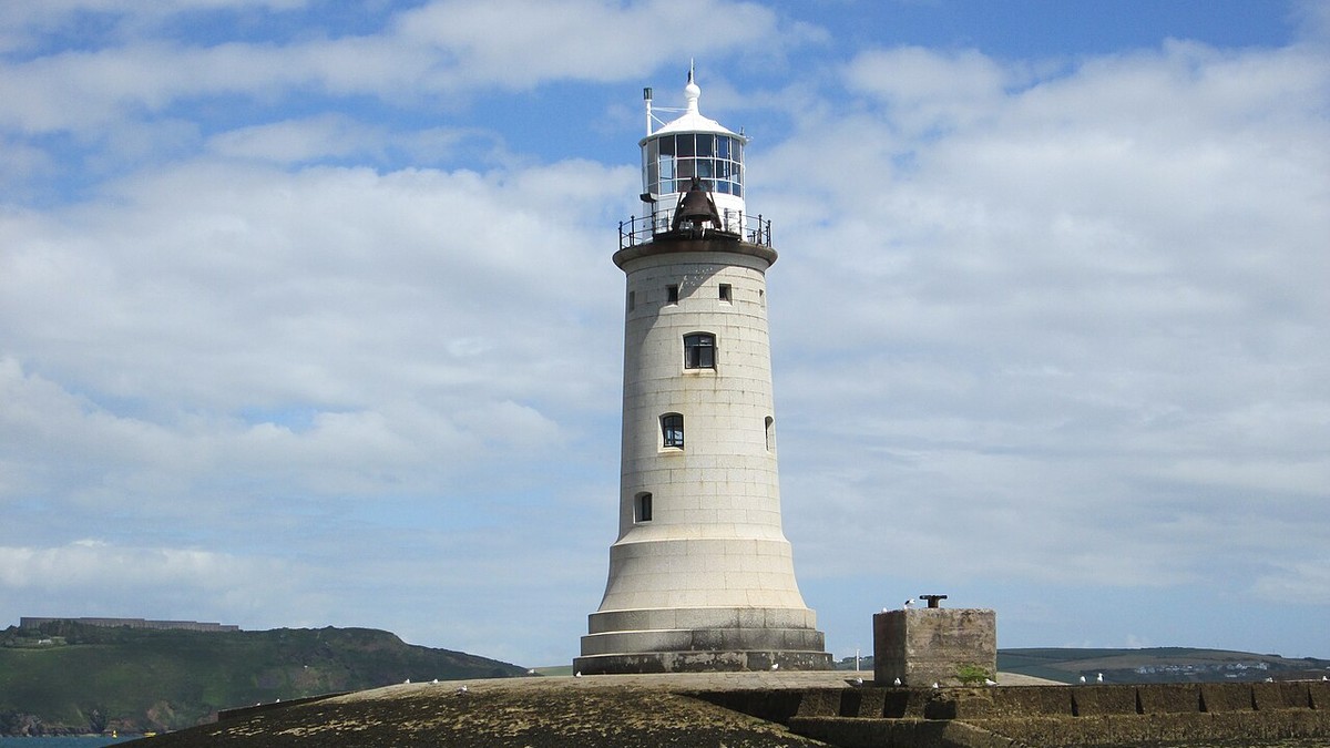
Plymouth Sound, situated on the south coast of Devon, was the primary western operational anchorage for the British Channel Fleet during its sustained naval blockade of the French naval arsenal at Brest. However, the Sound was wide open to the violent south-southwestern Atlantic gales that swept in past Mount Edgcumbe and the Mewstone. In a single storm in 1804, ten warships were driven ashore and wrecked.
In 1806, the British Admiralty commissioned civil engineer John Rennie, alongside surveyor Joseph Whidbey, to design an artificial breakwater across the middle of the Sound. Rennie’s bold proposal was to construct a freestanding, mile-long artificial stone island in the open ocean, situated 2.5 miles south of Plymouth Citadel in water depths ranging from 30 to 45 feet.
The Million-Ton Riprap Mountain
Construction began on August 12, 1812 (the birthday of the Prince Regent). Rennie rejected vertical masonry walls as impossible in the exposed Atlantic swells, choosing instead the rubble mound method. The Admiralty purchased the limestone quarries of Catdown, establishing a fleet of specialized hopper barges (vessels equipped with trapdoor bottoms) that dropped limestone blocks weighing from two to ten tons directly into the sea along the surveyed alignment.
The scale of the undertaking was unprecedented. Over a thirty-year construction period, more than 4.5 million tons of limestone were quarried, transported, and deposited on the seabed. The breakwater rose from a submerged base over 390 feet wide to a crest 30 feet wide standing ten feet above high water springs, measuring 5,100 feet (nearly one nautical mile) in overall length, flanked by two angled wings that curved inward to deflect waves away from the harbor entrances.
The Great Storm of 1824 and the Granite Glacis
The ultimate test of Rennie’s design occurred on the night of November 23, 1824, when the ‘Great Gale’ struck southern England with hurricane-force winds. The gigantic Atlantic storm waves tore into the breakwater, rolling over 200,000 tons of heavy limestone blocks from the seaward face completely over the crest into the inner sound.
Following this disaster, John Rennie’s son, Sir John Rennie, completed the structure by re-engineering the seaward slope into an ultra-low, 1-in-5 hydraulic glacis. The entire upper surface was paved with colossal granite ashlar blocks weighing up to 15 tons, scarphed together with dove-tailed joints and hydraulic Roman cement. The paved glacis allowed storm waves to roll smoothly up the ramp, exhausting their kinetic momentum without finding any perpendicular surface to impact.
⚓ Engineering Achievement: Plymouth Sound Breakwater
Completed in 1841 at a total cost exceeding £1.5 million, the Plymouth Breakwater transformed Plymouth Sound into one of the safest naval anchorages in the world. Still fully operational today under the care of the Ministry of Defence, it has sheltered over 100,000 ships over nearly two centuries of continuous storm defense.
3. The French Epic at Cherbourg: Cessart’s Cones and the Digue
While Britain fortified Plymouth, across the English Channel King Louis XVI of France embarked upon an even more audacious maritime project at Cherbourg. Situated on the northern tip of the Cotentin Peninsula, Cherbourg was strategically positioned directly opposite Portsmouth and the Solent, but possessed no natural harbor to protect a French invasion fleet or naval squadron.
In 1781, French military engineer Louis-Alexandre de Cessart proposed an extraordinary technological concept: the construction of a four-kilometer-long detached breakwater (the Digue de Cherbourg) using pre-fabricated floating timber cones (caissons coniques). Each cone was a colossal wooden timber frame measuring 45 meters (150 feet) in base diameter and 20 meters in height, constructed from thousands of oak and pine beams.
The Tragic Destruction of the Cones (1784–1789)
The execution of Cessart’s plan was a marvel of naval spectacle. Towed into the open roadstead by dozens of oared cutters, the giant hollow cones were flooded, sinking onto the seabed in a linear row. Once settled, hundreds of barges dumped hundreds of thousands of tons of stone into the center of the wooden cones to form a solid stone core.
However, Cessart severely underestimated the tearing horizontal shear forces of open Channel storms. In the brutal winter gales of 1788 and 1789, massive storm swells smashed into the wooden framework, stripping away the timber beams and washing out the internal stone ballast. When the French Revolution erupted in 1789, work ground to a complete halt, with Cessart’s cones destroyed.
Napoléon Bonaparte’s Monolithic Stone Wall
In 1802, First Consul Napoléon Bonaparte visited Cherbourg and declared that the breakwater must be completed at all costs to serve as a launchpad for the invasion of England: ‘We must recreate at Cherbourg the wonders of Egypt!’ Napoléon abandoned Cessart’s cones, directing civil engineer Joseph Cachin to build a massive stone rubble mound identical to Rennie’s Plymouth design, crowned by a continuous vertical masonry wall and fortified circular artillery forts.
Completed in 1853 under Emperor Napoléon III, the Digue de Cherbourg remains the longest detached breakwater in the world, measuring an astonishing 3,640 meters (2.26 miles) in length, holding back the full force of the English Channel and enclosing an artificial harbor of over 1,500 hectares.
4. The Invention of Artificial Concrete Armor: Tetrapods and Beyond
Throughout the nineteenth and early twentieth centuries, the primary constraint on rubble-mound breakwaters was rock availability. Constructing a deepwater breakwater required natural quarry stones weighing 20 to 50 tons to withstand open-ocean waves. Very few commercial quarries in the world could produce granite or basalt blocks of that magnitude in sufficient numbers.
The modern revolution in maritime civil engineering was born in 1950 at the Neyrpic laboratory in Grenoble, France, with the invention of the Tetrapod. Engineered by Pierre Danel, the tetrapod is a four-legged pre-cast concrete armor unit designed with organic geometry: four cylindrical legs radiating symmetrically from a central body in tetrahedral alignment.
Interlocking Geometry and Porosity Dissipation
When dumped randomly across a seaward breakwater slope, tetrapods naturally interlock with one another. Unlike smooth, flat rectangular stones that easily slide out of position under wave suction, tetrapods cannot be dislodged individually without moving the surrounding cluster.
Furthermore, their complex geometric shape creates a porous armor layer with a void ratio of nearly 50%. When a massive wave strikes a tetrapod revetment, the water rushes into the internal voids between the concrete legs, generating intense internal turbulence that dissipates over 60% of the wave energy before it ever reaches the core of the breakwater. The success of the tetrapod spawned an entire family of modern concrete armor units, including the Dolosse (South Africa, 1966), the Accropode (France, 1981), and the Xbloc (Netherlands, 2003).
5. The Future of Maritime Coastal Defense in the Era of Sea-Level Rise
In the twenty-first century, breakwater engineering faces its greatest challenge in human history. Accelerating climate change, rising global sea levels, and the increasing frequency and intensity of catastrophic oceanic storm surges threaten coastal infrastructure, commercial mega-container ports, and coastal population centers across the globe.
Modern coastal engineers are moving beyond static rock and concrete barriers, developing dynamic, nature-based breakwaters. Projects such as the Dutch ‘Sand Motor’ (Zandmotor) utilize natural wave and tidal currents to redistribute millions of cubic meters of offshore sand into dynamic, self-healing coastal barriers. Simultaneously, marine engineers are integrating artificial living reefs—constructing breakwater armor units with pH-neutral concrete seeded with oysters, mussels, and kelp forests that absorb wave energy while regenerating marine biodiversity.
From the Roman pozzolanic concrete caissons of Portus and the million-ton limestone mountain of John Rennie at Plymouth to the interlocked concrete tetrapods guarding modern mega-harbors, breakwater civil engineering stands as humanity’s ultimate protective shield along the contested frontier between terrestrial civilization and the untamed ocean.
6. Geotechnical Foundations and Liquefaction in Deepwater Breakwaters
The ultimate hidden vulnerability in marine breakwater engineering lies not above the water, but within the geotechnical soil strata of the seabed beneath the structure. When millions of tons of riprap or concrete armor are deposited on an offshore site—such as Plymouth Sound or Cherbourg—the immense deadweight exerts colossal compressive stresses upon marine silts and soft clays.
During severe hurricane gales, cyclic wave loading compounds these stresses. As colossal storm waves crash against the breakwater face, fluctuating hydrostatic pore pressures are transmitted deep into the seabed sediments. If the seabed consists of saturated fine sand or silt, this rapid cyclic pressure can trigger soil liquefaction: the sand grains lose contact with one another, the soil loses all shear strength, and the multi-ton breakwater embankment suddenly sinks or slides into the liquefying seabed. Modern coastal civil engineers prevent liquefaction failure by dredging soft muds down to bedrock and laying geotextile filtration mattresses beneath gravel foundation blankets.
| Geotechnical Hazard | Physical Causal Mechanism | Structural Failure Mode | Modern Engineering Mitigation |
|---|---|---|---|
| Soil Liquefaction | Cyclic wave pore-water pressure spikes | Breakwater sinks or slips into seabed | Geotextile filtration membranes & stone compaction |
| Toe Scour | Wave reflection turbulence at base of wall | Undermines foundation; wall tips forward | Heavy riprap toe berms and concrete mattresses |
| Internal Core Washing | Fine stones washed through armor voids | Cavitation and sinkholes in crest pavement | Graded filter layers (Quarry-run > Core > Armor) |
| Overtopping Crest Gouging | Massive green-water waves cresting over wall | Tears away rear sheltered roadway blocks | Recurved wave-deflecting parapet seawall crests |